HT Gasification of Biomass and Wastesby GP Green Energy |
DUAL FLUIDIZED BED (DFB) GASIFICATION |
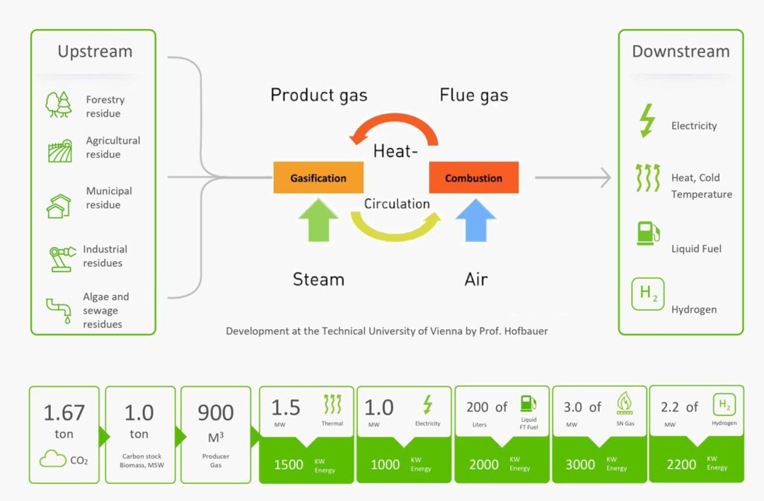
The Dual Fluidized bed (DFB) Steam Gasification process is considered as one of the most sophisticated processes in the world. It can convert 1 Ton of biomass or garbage (RDF) to –
|
Process |
 |
|
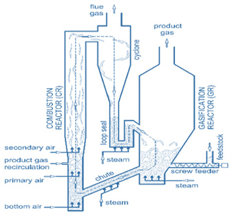
In the process, biomass is fed into the fluidized bed reactor through a rotary valve and a screw feeder. The FICFB (Fast Internal Circulating Fluidized Bed) Gasifier consists of two interconnecting zones – a gasification zone and a combustion zone. The gasification zone is fluidized with steam, which is generated from the waste heat of the process to produce a nitrogen free producer gas. The combustion zone is fluidized with air and delivers the heat for the gasification process via circulating bed material through a syphon. Here, combustion takes place of non-gasified carbon, which is transported from the gasification zone into the combustion zone. Product gas is used as an additional fuel to control the process temperatures. The heat required for the endothermic steam gasification reactions is transported by the bed material from the exothermic combustion chamber into the endothermic gasification chamber. This is how a nitrogen-free syn gas can be produced. |
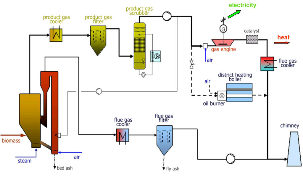
The resulting raw producer gas is cooled and cleaned by two stage cleaning system. Tar, dust, condensate etc. are removed by an oil scrubber. Scrubber liquid saturated with tar and condensate is vaporized and introduced into combustion zone of the gasifier. Waste heat is available during cooling of the syngas, which is effectively used for drying of the feedstock or any other application. Only dry ash with very low carbon comes out from the system and there is no liquid effluent. |
| Calorific Value | Efficiency | Plant Availability | Gas Quality (dry gas) | H2:CO |
| 12.5 - 13.5 MJ per Cubic Meter. | 25% electrical efficiency + 56.3% thermal efficiency = 81.3% in total |
90% (7,708 hours per year) | Hydrogen-38-45 Vol-%, Carbon Monoxide-22-25 Vol-%, Carbon dioxide-20-25 Vol-%, Methane-8-12 Vol-%, Nitrogen-2-3 Vol-% |
from 1.5 to 2:1 |
Advantages
Fuel Tested
50% tree and shrub clippings – 50% softwood pallets, 50% leaves – 50% softwood pallets , 40% straw – 60% softwood pallets, 50% Municipal solid waste (MSW) – 50% softwood pallets, 50% SLF – 50% softwood pallets, 20% PE – 80% PET, 40% PE – 60% PS, 75% MSW – 25% Lignite
GREEN HYDROGEN (GH2)From a DFB Gasifier the produced synthesis gas, which has high contents of hydrogen and carbon monoxide, is highly suitable for hydrogen production. High efficiencies of more than 60% can be reached by generating hydrogen from biomass and total efficiencies of up to 80% are possible by utilization of waste heat. Here, 320 kW of extrinsic energy are required for 1000 kWh of H₂. By comparison, generating the same amount of H₂ via electrolysis would need 3000 kWh of energy. Hydrogen plant through above technology is most effective for production decentrally at low cost. This can be installed close to highways or traffic model centers, where biomass is available locally to avoid transportation of hydrogen. A fully distributed network can be designed at the places where trucks, buses and passenger cars are widely available. |
ProcessFor hydrogen production, the syngas generated out of DFB Gasifier needs further processing. First, filter to remove dust particles, thereafter a water gas shift stage to enhance the hydrogen output, an organic scrubber to remove water and tar out of the syngas, a CO₂ removal stage to separate sour gas components, a hydrogen purification unit to produce high quality hydrogen and finally, a tail gas reforming step to enhance the efficiency of the plant. 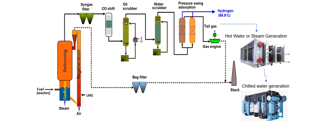
The main components of the GH₂ plant are shown in the diagram below. The tar-rich syngas from DFB gasifier is mixed with recycled gas from the steam reformer and sent over a two-staged water gas shift reactor (orange). A high temperature sour gas shift catalyst, based on iron and chromium, is used for the water gas shift process. The carbon monoxide and steam in the gas are converted to carbon dioxide and hydrogen according to water gas shift equation: CO + H₂0 <–> CO₂ + H₂
The CO shift process is operated at atmospheric pressure and temperature up to 450° C at the outlet of the shift reactors. After the gas has passed the water gas shift stage, it enters a two-stage organic scrubber (yellow), operated with rape seed methyl ester (RME). In this scrubber, tars are removed and water is condensed down to 3% moisture content in the syngas. The scrubber fluid has to be cooled to ensure the necessary separation efficiency. Then, the gas is compressed and sour gas components (CO₂, H₂S) are removed by an amine scrubber (green) operated at a pressure of 23 bars. The temperature in the CO₂ absorber is set at 40° C. With a pressure swing adsorption (blue), the hydrogen of the gas is recovered by adsorption of impurities on a molecular sieve and activated carbon. This hydrogen has high purity and can be further used for energy generation. The tail gas of the PSA, which has a high content of hydrocarbons, is splitted, the main part is sent in to a steam reformer (red) to covert the hydrocarbons in to carbon monoxide, carbon dioxide and hydrogen according to the general steam reforming equation : CₓHᵧ + ₓH₂O <–> (ₓ₊ᵧ/₂) H₂ + CO The reformed gas is sent back to the water gas shift stage to achieve a better efficiency. The other part of the tail gas is sent back to the combustion zone of the gasifier represent the amount of gas necessary for heating the reformer. |
Composition of the syngas after the steam reformer:
|
Quality of the prodiced hydrogen
|
|
The impurities were caused by nitrogen, which was used for online cleaning of bag filters in the gasifier. These cleaning activities can be performed with the separated carbon dioxide. This would result in low nitrogen content in the producer gas. |
SYNTHETIC NATURAL GAS (Bio-SNG)Beside environmental aspects, high oil prices increase the necessity of the use of renewable energy sources. Biomass is a renewable energy source, which allows a sustainable utilization for several reasons. Its carbon dioxide neutrality and high availability make economic usage of this source possible. Rather for generating heat and power, a more sophisticated way of using biomass is transforming it into a secondary energy source by liquefaction and gasification. The product of the gasification process – is a medium calorific product gas, which is nearly free from nitrogen and has a H₂ : CO ration favorable for synthesis processes. Therefore, the product gas can be converted into a Synthetic Natural Gas (Bio-SNG). The compressed Bio-SNG can be stored in a fuelling station to supply energy to CNG vehicles. It can also be injected to the natural gas grid. |
ProcessFor the production of Bio-SNG from biomass, syngas from DFB gasifier is very effective as it is high in hydrogen (apprx. 40 vol.% (dry)), low in nitrogen (< 2 vol.% (dry)) and contains a rather high amount of methane (apprx. 9 vol.% (dry)). The product gas generated by the gasifier is cleaned from dust (ash) and tar after sensible heat recovery. This is carried out by a bag house filter and a subsequent scrubber using rape seed methyl ester (RME) as a solvent for the tars. 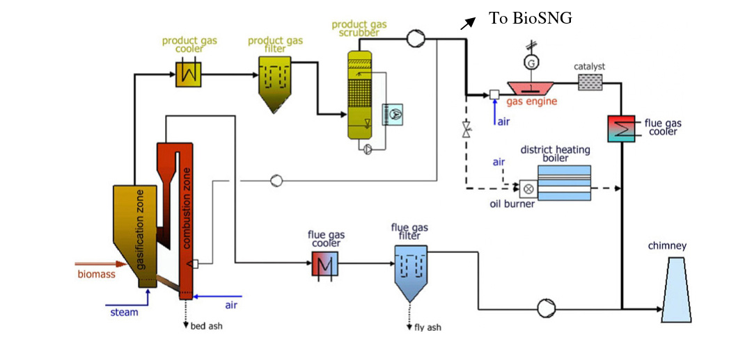
In the Bio-SNG production, additional cleaning is done. Here, several scrubbing stages are installed to avoid the transport of substances with the product gas that would damage the methanation catalyst. Methanation reactions: |
| CO + 3 H₂ <–> CH₄ + H₂O | CO₂ + 4 H₂ <–> CH₄ + 2H₂O | CO + H₂O <–> H₂ + CO₂ | C₂H₄ + 2H₂O <–> 2CO + 4H₂ |
| CO methanation reaction | CO2 methanation reaction | Water-gas shift reaction | Reforming reaction |
| Exothermal | Exothermal | Exothermal | Endothermal |
The conditioned product gas enters the methanation reactor where the CH₄ content is increased essentially. Then the raw SNG (the gas exiting the methanation reactor) passes several purification steps to increase the methane content up to a ratio to meet the regulations for feeding into the natural gas grid or for fuelling station.
The required raw SNG upgrading steps consists of ammonia scrubbing (sulphuric acid), CO₂ scrubbing (using amine), drying (using condensation and glycol scrubbing) as well as (excess) hydrogen separation and recirculation using membrane technology. Enough cares have been taken to fulfill health and safety requirements.